WIP POST
I realized I forgot how I setup my pit for the F-18 a few month ago and DCS method of exporting cockpit screen is not so intuitive, especially when you don't mess around with LUA files often
So I wanted to have the method published somewhere so I can back to it in due time and I'm sure it can also help a few of you guys.
First this is mostly to enable the Mfds. I'm not fiddling around with external views and other stuff but I focus mainly on cockpit screens like MFDs, MPCD, IFEI, etc etc
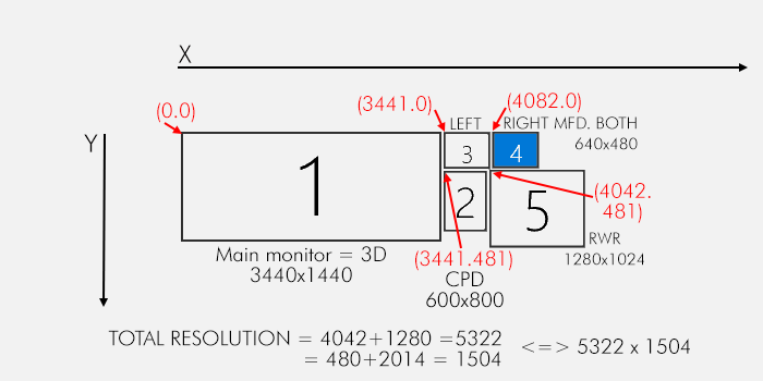
1. Knowing your screen coordinate systemThe first step to any multi-monitor hassle is to get a firm grip of your multi-monitor configuration system.
I obviously can't detail yours and I will use mine as an example. You obviously have to the the math for yours.
My configuration is the same for BMS and DCS and is as follow:
Main screen for 3D: 3440x1440 = SCREEN ID 1
2 MFDs screens each at 640x480 placed right of my main, aligned with the top edge = SCREEN ID 3 and 4
1 600x800 (portrait) CPD screen placed right of my main, aligned with the left MFD = SCREEN ID 2
1 RWR screen 1280x1024 placed right of the CPD on the same vertical alignement = SCREEN ID 5
This gives me a total combined resolution of 5322x1504 pixels
You have to calculate each top left corner coordinate in pixels. These are given in red in the image below
piece of advice: make a graphic, with screen arrangement and resolution with top left coordinates and save it.
 2. Knowing how DCS works
DCS uses lua files wich are basically text programming file you can edit with Notepad+
The main file you need can be called however you want it and has to be located in your \Config\MonitorSetup folder.
There are a few readily available and the easiest is to start with either one and edit it according to our needs or create one from scratch.
Start your file with the header
_ = function(p) return p; end;
 name = _('RD_pit');
 Description = 'my 5 screens pit setup. Main is 0.0 3440x1440';
 Viewports =
Don't touch the first line.
Second line is the name of your configuration. Basically anything you want. Here RD_pit
Third line is the description you can edit at will.
Fourth line is the start of the viewports declaration. Don't touch this one
DCS manages screen by Viewports which needs to have a top left coordinate and a resolution in pixel.
Basically if you want to extract a specific display to a screen in your setup you have to create a viewport.
First thing you have to know is the name DCS expect for each viewport.
These are either hardcoded for the most common ones of you could probably make your own name but that's outside the scope of this tutorial.
Luckily names of the most common ones should be the same.
The F-16 has two MFD and the F-18 has 3. The left one is called the same in different aircraft. So is the right and so is the centre
What basically means is that if you declare it with the DCS name, the export will work in all aircraft config using the same display configuration.
For instance if you declare LEFT and RIGHT MFCD then these two will be active with all aircraft having 2 Mfds like the F-16, F-18, A-10 etc etc.
Of course aircraft can also have specific displays like the F-18 can export the IFEI which doesn't exist on the F-16.
The F-16 has the DED_VIEW.
These will obviously work only for their relevant aircraft.
Here are the main DCS viewports names
The main screen is called
CENTERLeft MFD is called
LEFT_MFCDRight MFD is called
RIGHT_MFCDCentre MFD is called
CENTER_MFCDEach of these will need a viewport declaration in the LUA file which will start right after the "viewports" = line.
How to setup a lua viewport
  LEFT_MFCD =
	{
		x = 3521;
		y = 0;
		width = 480;
		height = 480;
	}
The above declares my LEFT MFD at coordinates (3521,0) with a resolution of 480x480 pixels
Why 3521?
The left MFD screen starts at (3441,0) but the screen res is 640x480.
I don't want the MFD to be out of ratio so I can't start the display export on top left coordinates of the screen. I need to calculate the ideal starting point taking into consideration the square projection of the left MFD.
Since I export at 480x480. I calculate (640-480)/2=80 pixel.
I add that to the the top left screen coordinate (3441+80)= 3521
Since the top of all screens are aligned, Y remains 0.
The top left corner of my extracted left MFD will thus be (3521,0)
And the extracted left MFD will be 480x480 pixels.
You do the same for the RIGHT MFD which doing the same calculations will give you (for the screen configuration of this example): 4162 = 3441+640+1+80
 RIGHT_MFCD =
	{
		x = 4162;
		y = 0;
		width = 480;
		height = 480;
	}
Now let's say I wanted also to export the center MPCD for the hornet on my screen 2 (CPD)
 CENTER_MFCD =
	{
		x = 3441;
		y = 481;
		width = 600;
		height = 600;
	}
That is a display size of 600x600pixels and the top left corner set at the same coordinates as my CPD screen declaration.
It would also give me an empty 200 pixel high zone below the screen where I could for instance extract the IFEI... or any other required display/viewport.
Please note, if you setup your system for BMS RTT, you basically use the VERY same coordinates you declared in your RTTclient.ini file.The MAIN view has to be declared as well.
It's called CENTER in DCS and is the GUI and 3D view. In this example I want my Samsung 34inch screen to display DCS GUI and DCS 3D view.
{
 Center =
	{
		x = 0;
		y = 0;
		width = 3440;
		height = 1440;
		viewDx = 0;
		viewDy = 0;
		aspect = 2.388889;
	}
 }
The display start at coordinates (0.0) and has a resolution of 3440x1440. The aspect has been calculated (3440 divided by 1440)
and the viewDx and viewDy are left untouched. I never bothered with these
You could also declare it this way:
{
     Center =
     {
          x = 0;
          y = 0;
          width = screen.width;
          height = screen.height;
          viewDx = 0;
          viewDy = 0;
          aspect = screen.aspect;
     }
}
No resolution given but the info will then (I assume) be taken from the multi screen Windows data.
We still have to tell DCS where we want to have the GUI and 3D view to be exactly displayed
this is done by adding these two lines at the end of the lua file
UIMainView = Viewports.Center
GU_MAIN_VIEWPORT = Viewports.Center
It sets these views to the CENTRE viewport declared above, hence in this example screen 1 = the samsung 34 inch.
Here's the Full lua file for your review:
_ = function(p) return p; end;
 name = _('RD_pit');
 Description = 'my 5 screens pit setup. Main is 0.0 3440x1440';
 Viewports =
 {
 Center =
	{
		x = 0;
		y = 0;
		width = 3440;
		height = 1440;
		viewDx = 0;
		viewDy = 0;
		aspect = 2.388889;
	}
 }

 LEFT_MFCD =
	{
		x = 3521;
		y = 0;
		width = 480;
		height = 480;
	}

 RIGHT_MFCD =
	{
		x = 4162;
		y = 0;
		width = 480;
		height = 480;
	}

 CENTER_MFCD =
	{
		x = 3441;
		y = 481;
		width = 600;
		height = 600;
	}

  RWR =
	{
		x = 4042;
		y = 481;
		width = 1280;
		height = 1024;
	}


UIMainView = Viewports.Center
GU_MAIN_VIEWPORT = Viewports.Center
Launch DCS and open the system page from the configuration menu
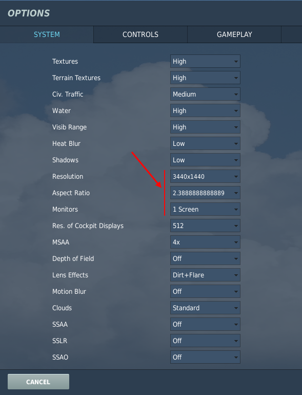
Initially when entering the system page, it is set to 1 screen, 3440x1440 resolution with matching aspect ratio.
Click first on the monitor option (1 screen) down arrow to see what are the possible options and from that list find the name you gave to your lua file (RD_pit).
If you cannot find that name listed, you probably didn't copy the file at the best place *
Next change the resolution line manually by entering your combined total resolution calculated early in this tutorial (5322x1504)
The aspect ratio will be calculated automatically.

Click OK and DCS will restart.
If all goes fine DCS will now be displayed on your main screen and all the other screen will be black while you're in the UI.
Start a mission and see the extracted displays.
* DCS has two possible locations: saved games or straight into the install folders.
And of course some of us may use stable and beta version alongside, making a total of 4 possible place to store these files.
I prefer to have them straight to the install folder. but you do as you see fit.


 Guests: 56
 Hidden: 0
 Users: 0